Maytag Neptune MAH3000AWW
Please see safety cautions


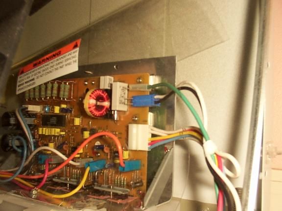
Neptune Motor Control Board Connectors
position mouse over connector for identification

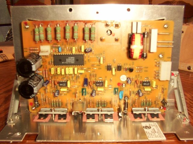
Neptune Motor Control Board Major Components
position mouse over component for identification

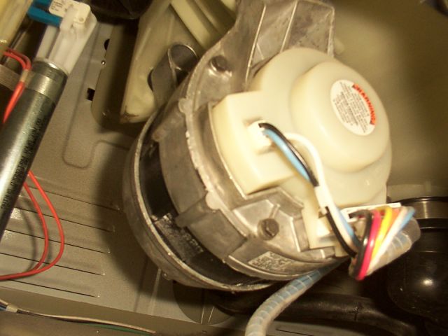
Neptune Motor Connectors
position mouse over component for identification

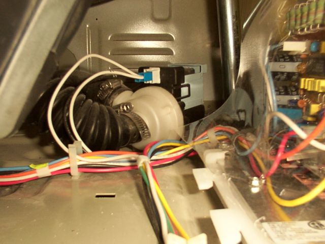
Neptune Pump Placement
position mouse over component for identification


All information on this page provided for reference only.

CAUTION: Refer service to qualified personnel.


This equipment contains dangerous mechanical and electrical devices. Machine should be unplugged from electrical power source before servicing. Dangerous moving parts, potential of pinch points and sharp edges, lethal electrical potentials, and pressurized fluids are present inside this unit.

Please read user manual.


Home
Top
Connector J4 120 vac to board fuse Phase B to Motor - White Wire Phase A to Motor - Black Wire Phase C to Motor - Yellow Wire Phase C to Motor - Orange Wire Phase A to Motor - Blue Wire Ground Wire Tachometer signal from Motor Phase B to Motor - Red Wire Wiring harness to Main Control Board Wiring harness to Motor Fuse Phase C MOSFETs - IRF644 Phase B MOSFETs - IRF644 Phase A MOSFETs - IRF644 Phase A IR2101- High/Low side driver Phase B IR2101- High/Low side driver Phase C IR2101- High/Low side driver Control Chip - specs unknown Full Wave Bridge Rectifier 1800 Ohm (1.8 K) Power Resistors Freewheel Diode Freewheel Diode Freewheel Diode Freewheel Diode Freewheel Diode Freewheel Diode OptoCoupler - SFH610A OptoCoupler - SFH610A NPN Transistor - 2SC1213A Tachometer Feedback Connector Motor Power Connector Drum travel 'wobble' limit switch Drum suspension strut Drum drain boot Switched-Reluctance Motor Neptune Pump Assembly Motor Control Board Tub Suspension Strut

Aircraft, aviation, planes, jets, turboprops, helicopters, avionics